Hydraulic balancing should ensure that the flow through a thermal unit never exceeds the design flow and that the - by BMS or stand-alone thermostat - required flow is proved. If the flow is different from these criteria, the system balancing will be incorrect which effectively will be hampering the indoor comfort and building energy consumption.
The most common problems in terms of achieving the above-described balancing are as follows:
- Pressure fluctuations result in flow fluctuations.
- Valve authority - the Control Valve (CV) and the Double Regulating Valve (DRV) are fighting for the pressure drop and thereby the authority.
Description of DPCV + DRV + CV System
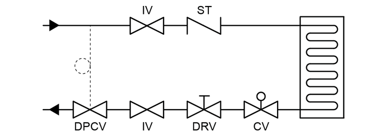
The trinity consisting of a Differential Pressure Control Valve (DPCV), a Double Regulating Valve (DRV) and a Control Valve (CV) in a coil layout typically looks as shown in figure 1.

Component Description
Differential Pressure Control Valve, DPCV
The DPCV is designed to maintain a constant differential pressure between 2 specified points. DPCVs are normally used in strategic locations in the system in order to isolate specific system sections and thereby minimize the pressure fluctuations in the overall system. How the pressure is distributed “behind” the 2 specific points is not controlled by the DPCV. A DPCV can therefore only be used to maintain a constant ΔP over an area, which normally contains a set of thermal units as per figure 1.
Double Regulating Valve, DRV
The DRV is installed to balance the system which, in a combination with a modulating Control Valve, effectively means that the valve is to ensure that the maximum flow is never exceeded. The DRV is pressure dependent, and any pressure fluctuation will result in changed maximum flow - lower differential pressure across the unit will result in lower flow rates and vice versa as per the formula

Control Valve, CV
The CV is installed to allow the BMS system or stand-alone thermostat units to control and modulate the flow rate anywhere between 0% and 100% of the design flow. The CV modulates the flow by adjusting the CV opening and thereby changing the flow. As the valve is also operating within the formula Q = Kv * √ΔP, any pressure fluctuation will result in changing flow.
In the configuration shown in figure 1 the DPCV is used to control the differential pressure across the coil arrangement, the DRV is used to set the maximum flow and the CV is used to ensure modulation within 0-100% of the design flow.
DPCVs are normally used for riser, branches, or coils and the further away from the coil it is installed - and thereby expanding the number of coils it controls - the smaller the impact it will have on the individual coil. In case the DPCV is used on a branch - or further downstream - the CV will have to change position to compensate for pressure fluctuations providing an unstable ΔT in the coil.
The CV and the DRV will both try to control the flow rate - a controversy described by the CV authority. The valve authority is aimed at around 50%, which is an industrial guideline. In order to achieve such authority, the pressure drop across the balancing valve will have to be calculated and based on this is the Kv-value for the CV selected. Due to limited Kv-options available, the control valve is often oversized which again will result in reduced authority and thereby reduced controllability.
Description of PICV system
The common Pressure Independent Control Valve (PICV) in a coil layout typically looks as shown in figure 2.
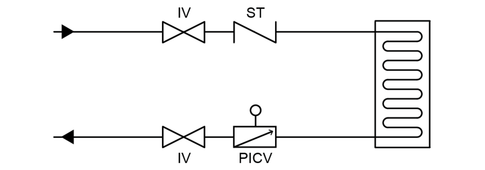
- PICV = Pressure Independent Control Valve
- IV = Isolating Valve
- ST = Strainer
The PICV is basically a DPCV, a CV and a dynamic balancing valve built into one unit. The dynamic valve acts as an overflow preventer ensuring that overflow is never present in the coil. The DPCV ensures that the differential pressure across the CV section remains constant and that flow therefore does not change with system pressure fluctuations. Due to the fact that the differential pressure is absorbed inside the PICV, the valve will always have 100% authority making pressure drop calculations obsolete. Furthermore, the PICV is self-balancing meaning that no balancing - or re-balancing - of the system is required.
Comparison
The usage of a DPCV + DRV + CV solution have several problems, that affects the performance of the system and the lifespan of particularly the CV. All the listed problems below will be solved if the trinity is replaced with a PICV valve.
- The differential pressure will despite the introduction of DPCVs still fluctuate within the series of thermal units mounted “behind” the DPCV.
- Any system pressure fluctuations must be handled by CV movement, resulting in more wear and reduced actuator life.
- The flow through the DRV will fluctuate with changes in load conditions within the series of thermal units located in the sub-system. Higher pressure than designed will result in overflow.
- The control valve will have to fight the DRV regarding the pressure drop and thereby control authority of the flow. During design, an authority of 50% is targeted, but this value will in practice normally be substantially lower as both CV and coil are commonly oversized. Furthermore, the authority equation only includes the specific coil system and not the full system, meaning that pressure overtaken from other parts of the system is not included in the theoretical assessment.
- System has to be balanced and over time re-balanced to perform optimally.
- DRVs require valves installed on main, riser, branch and coil resulting in higher number of valves and thereby increased system pressure drop.
- CV pressure drop has to be minimum 2 times the DRV pressure drop to ensure authority resulting in relatively large pressure drops and thereby larger energy consumption.
Conclusion
The closer the pressure controlling functions are to the coil the more effective it is and therefore it is recommended that DPCVs are installed on each coil for optimal performance. A PICV has the function of maintaining a constant differential pressure over a specific area built in and therefore by definition it is applied on the coil where used.
PICVs always have 100% authority, due to the pressure independent function, whereas the CV and DRV are pressure dependent meaning that 100% authority can never be obtained. High authorities can only be achieved through high resistance in the CV, with high pressure drop and thereby high energy consumption as a result.
CVs must be selected as per pressure drop calculation introducing a time-consuming selection process. PICVs are selected based on the pipe diameter, flow and pressure drop and are therefore less dependent on manual errors and free from time-consuming calculations. Also, in a PICV solution, fewer valves are required resulting in lower pressure drop and reduced risk of pipe leakage. Furthermore, the PICV solution is self-balancing meaning that time spent on balancing / commissioning is substantially reduced.
FlowCon 最新文章
显示所有文章


Insert Means Flexibility
Flexibility across every phase. Stable HVAC performance, without compromise in every outcome

Sustainability and PICVs
Sustainability in HVAC is no longer optional - it is fundamental to responsible system design